
The Yaesu FT-891: a name that frequently pops up in discussions about modern HF transceivers, and for good reason. This little powerhouse packs a serious punch, boasting 100W output in a remarkably compact and portable package, making it a favorite for SOTA, POTA, mobile enthusiasts and even as a first base station.
Its excellent receiver design, featuring solid DSP filtering (including a 3kHz roofing filter for enhanced out-of-band rejection) and 32-bit DSP processing - capabilities often reserved for much larger and more expensive radios. Add to that its all-mode HF+50MHz capability, a large, easy-to-read display, and a convenient detachable control unit, and it's easy to see why it's so popular.

However, this wealth of features and power comes with a trade-off. Beneath its sleek exterior lies a menu system brimming with functions. While incredibly versatile, this depth means the FT-891 needs better understanding, especially for operators new to this rig, the Yaesu ecosystem, or amateur radio in general. Many essential functions are accessed through layered menus, and the sheer number of options can initially feel overwhelming or unintuitive if you're just starting out.
In this blog post, I'll delve into the features that make the Yaesu FT-891 shine, provide guidance to help new users navigate its complex menu system, and share hints, tips and tricks to truly unlock its potential. For those willing to invest the time, the FT-891 rewards with flexibility and performance that’s hard to match in its class. My goal is to help you enhance your enjoyment and get the most out of this fantastic radio. Let's explore!
Tip #1: Powering Your FT-891 – Getting it right for Peak Performance
First things first: the Yaesu FT-891 is quite specific about its electrical diet. To ensure optimal performance and avoid potential damage, it's crucial to maintain an operating voltage strictly between 11.73 volts and 15.87 volts. Straying outside this range isn't just a suggestion – it can harm your radio, so pay close attention!
When it comes to feeding your FT-891, you've got two main paths: a mains power supply unit (PSU) or a battery.
Power Supply Units (PSUs): For home base operation, a good quality PSU is essential. However, be aware that some cheaper switching power supplies (SPS) can introduce unwanted noise into your receiver, manifesting as buzzes or birdies across the bands. While the FT-891's built-in Noise Blanker (NB) function can sometimes help mitigate this, it's often a better long-term strategy to invest in a well-regarded linear PSU or a high-quality, radio-friendly switching supply from the outset. This can save you a lot of frustration chasing down interference.
Battery Power – The Portable Choice: For portable operations (SOTA, POTA, or just out in the field), batteries are king. But not all batteries are created equal for the demanding FT-891:
- Sealed Lead Acid (SLA) Batteries: A Word of Caution. While common and often inexpensive, SLA batteries can be problematic. Their voltage can sag significantly under load, especially as they discharge. It's very possible for an SLA to drop below the critical 11.73V threshold during transmit cycles, even if it read a higher voltage at rest. This can lead to erratic radio behavior, unexpected shutdowns, or the radio automatically reducing power. For this reason, many experienced operators advise against using SLA batteries with the FT-891.
- LiFePO4 (Lithium Iron Phosphate) Batteries: The Recommended Choice. These are the go-to for modern portable radio operations. LiFePO4 batteries maintain a much more stable voltage throughout their discharge cycle, staying well within the FT-891's preferred operating range for a significantly longer portion of their capacity. This means more consistent performance and less worry about under-voltage issues.
- The Weak Battery Problem: Regardless of type, remember that an old, tired, or undersized battery (even a LiFePO4 that's past its prime or simply too small for the job) might not be able to sustain the current draw when transmitting at full power (up to 20-23 amps!). If the radio senses the voltage dropping too low under load, it will automatically reduce its output power to protect itself. If you're consistently not getting your full 100 watts out, an inadequate power source is a prime suspect.
Monitoring Your Voltage: So, how do you keep an eye on this vital voltage?
- Radio Display: The FT-891 itself offers a brief glimpse of the input voltage in the lower right corner of the display when you first power it on. Unfortunately, as many users wish, it's not a continuous display.
- External Power Analyzer: Highly Recommended! For reliable, real-time monitoring, especially when operating from a battery, investing in an external Power Analyzer is a game-changer. These handy devices sit in-line between your battery and radio, showing you the live voltage (and often current, power, and energy used) as you operate, particularly as you transmit. This gives you a clear indication if your battery is starting to struggle under load before it becomes a problem or your radio starts reducing power.
Practical Power Connection Tip: A very useful modification is to make a power cable pigtail. This involves taking the supplied Yaesu 4-pin power connector and wiring it to a more universal and robust connector of your choice. Anderson PowerPoles are extremely popular in the amateur radio community for their reliability and ease of use, but XT60 connectors are also a solid option. This allows for quick, secure connections and can make managing cables in the field much easier – you could even fix the new connector to a guard rail or part of your portable setup for added stability and strain relief.
The DIY Anderson PowerPole Direct Upgrade
For those standardized on Anderson PowerPoles and comfortable with a bit of DIY, directly replacing the FT-891's stock 4-pin power connector with a PowerPole panel-mount connector is an excellent and highly recommended upgrade. This provides a secure, standardized, and highly reliable power connection directly on the radio chassis.
As Roy (F4LBR) shares:
"I went the Anderson PowerPole route and swapped the Yaesu connector for this dedicated one. I can unreservedly recommend this modification for all the PowerPole users."
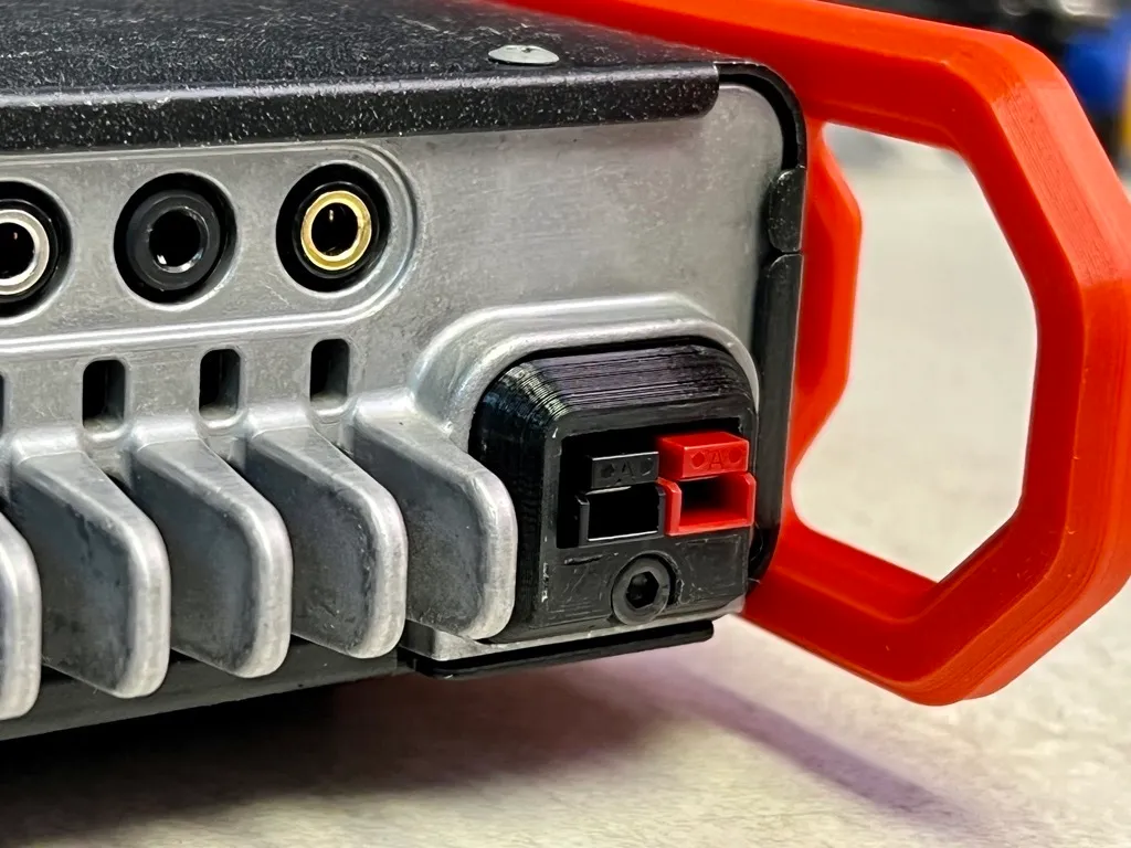 |
| Source: https://www.printables.com/model/418238-yaesu-ft-891-powerpole-conversion |
If you're interested in undertaking this modification yourself, there are some fantastic community resources available:
- GitHub Project by N0BOY (FT891_powerpole):
- Link:
https://github.com/N0BOY/FT891_powerpole - What it offers: This repository provides comprehensive details for the conversion. You'll likely find instructions, a bill of materials (parts list), and potentially schematics or photos guiding you through the process of creating and installing your own PowerPole connector assembly into the FT-891. This is an invaluable resource for understanding the technical aspects of the mod.
- 3D Printable Model on Printables.com:
- Link:
https://www.printables.com/model/418238-yaesu-ft-891-powerpole-conversion - What it offers: This link provides the 3D model file (e.g., STL) for the PowerPole housing specifically designed to fit the FT-891. If you have access to a 3D printer, you can print this part yourself, which is a key component of the conversion. The page may also include print settings recommendations and photos of the finished print.
Tip #2: Understanding and Managing Your FT-891's Power Output
The Yaesu FT-891 is renowned for its robust 100-watt output on SSB, CW, Data, and FM modes (and a healthy 25W on AM). This impressive power is reliably delivered thanks to careful circuit design, efficient thermostatically-controlled dual internal fans, and a die-cast heat-transferring chassis, ensuring stability even during prolonged transmissions.
Now, let's talk about adjusting that power. Unlike some radios with a dedicated front-panel power knob (oh, how we sometimes wish!), the FT-891 requires a dive into its menu system. You'll find the power settings under the TX GNRL section, specifically menu items 16-01 through 16-06. It's crucial to select the correct menu item for the specific mode and band (HF or 50MHz) you intend to operate on:
| Menu Number | Name | Purpose |
|---|---|---|
| 16-01 | HF SSB PWR | HF SSB mode maximum power |
| 16-02 | HF AM PWR | HF AM mode maximum power |
| 16-03 | HF PWR | HF CW, Data, and FM mode maximum power |
| 16-04 | 50M SSB PWR | 50 MHz SSB mode maximum power |
| 16-05 | 50M AM PWR | 50 MHz AM mode maximum power |
| 16-06 | 50M PWR | 50 MHz CW, Data, and FM mode maximum power |
Yes, it can feel a bit convoluted having separate settings for each mode and band group when a single control might seem more intuitive. This is a common point of discussion among FT-891 users – menus, menus, and yes, more menus!
But here’s a crucial point: while having 100W at your disposal is fantastic, you often won't need to run at full power, nor will significantly more power always be the magic bullet for better communication. Signal strength on the receiving end doesn't increase linearly with your transmit power; it's logarithmic. For example, to make your signal one S-unit stronger (a noticeable but not always game-changing difference), you'd typically need to quadruple your power (e.g., going from 25W to 100W). Going from 100W to, say, 200W with an external amplifier might only yield about half an S-unit improvement on the other end.
In most situations, especially for portable or QRP-minded operations, reducing power can save your battery, reduce stress on the radio, and often still get the job done effectively. For truly significant improvements in both transmitting and receiving, your focus should often be on a better, more resonant antenna system or optimizing the radio's receiver settings (like IF shift, contour, DSP noise reduction, etc.), which we'll be covering in following tips.
So, while knowing how to adjust your FT-891's power output is essential, remember that it's just one tool in your arsenal. Use it wisely, and don't forget the bigger impact of your antenna and receiver skills!
Tip #3: Taming the Noise Beast – Physical Setups to Quiet Your Shack (and Car!)
Before we even dive deep into the FT-891's internal noise-fighting functions, there's a lot you can do externally to reduce Radio Frequency Interference (RFI) and improve your reception. A quiet receiver starts with a quiet environment. The FT-891, like many modern sensitive receivers, can be particularly susceptible to RFI from various household and vehicle electronics, especially LED lighting.
The LED Menace – Even When "Off"! A surprising and often overlooked culprit can be LED lights and their power supplies. Many operators have found that LEDs, even when they appear to be turned off but are still plugged into the socket, can generate enough RFI to raise your noise floor by 1-2 S-units! If you're chasing noise, make it a habit to unplug nearby LED lamps and devices completely as a first troubleshooting step.
Now, let's look at other physical strategies:
1. Chokes and Ferrites – Your First Line of Defense: Common mode currents traveling on the outside of your coax shield or other cables are a major source of noise pickup.
- Feedline Choke (1:1 Current Balun/Choke): Install a good quality 1:1 current choke on your coaxial feedline.
- Placement: Ideally, place this close to the feedpoint of your antenna. This helps block common mode currents from traveling back down the shield towards your radio.
- Construction: Use a proper ferrite core (e.g., FT240-43 for general HF, or FT240-31 for lower HF bands/more challenging noise) with 9–13 turns of your coax (like RG58, RG8X, or H155).
- Clamp-On Ferrites: Don't stop at the coax! Use additional clamp-on ferrites on:
- Power supply cables (both AC and DC sides if possible)
- Microphone cords
- USB cables (if connecting to a computer)
- Other accessory cables
- Mix 31 or 43 ferrite material is generally effective for these applications. Snap them on, or loop the cable through them a few times if the ferrite size allows.
2. Strategic Antenna Placement: Where you put your antenna matters immensely for noise reduction.
- Distance is Key: Keep your antenna at least 1.5–2 meters (5-7 feet) away from building walls, metal surfaces like gutters, siding, and air conditioning units.
- Go High: Mount your antenna as high as practically possible. Higher elevation generally reduces coupling with local, ground-level noise sources.
- Avoid Parallel Runs: Try to avoid routing your antenna feedline or the antenna itself parallel and in close proximity to house wiring, other metallic elements, or known noise-generating devices.
3. Solid Grounding and RF Earthing: Proper grounding is crucial for safety and can significantly help with RFI.
- Antenna Ground: If your antenna design requires it (like many verticals), connect its feedpoint or radials to a real earth ground (e.g., one or more ground rods driven into moist soil).
- Radio Chassis Ground: Connect your FT-891's chassis ground terminal to the same ground rod system as your antenna, using a short, thick wire or copper braid. This helps minimize ground loops, which can be noise pathways.
- Quality Connections: Use short, low-inductance conductors (copper braid is excellent, solid heavy gauge wire is good) for all grounding connections.
4. Clean Power Supply (Revisited): We touched on this in Tip #1, but it's worth reiterating in the context of noise.
- Low-Noise PSU: Use a clean, low-noise power supply. Linear power supplies are often inherently quieter, but well-designed, radio-specific switching power supplies (like the Jetfon PC-35 SW or similar) can also be very good.
- Filter Noisy SMPS: If you must use a generic switched-mode power supply (SMPS) that you suspect is noisy, ensure it's properly filtered. Adding ferrite beads or toroids to its DC output cable (and sometimes even the AC input cable) can help block conducted RFI.
5. In-Car Specific Noise Tips: Mobile operation presents its own unique noise challenges.
- LEDs Off: As mentioned, turn off all LED lighting in the vehicle during operation – dome lights, dashboard accents, aftermarket additions are all potential RFI sources.
- Engine Off (If Possible): If you're stationary, consider turning off the engine. The alternator, ignition system, or Engine Control Unit (ECU) can introduce significant noise.
- Vehicle Bonding (For Dedicated Setups): For more permanent mobile HF installations, bonding various vehicle body panels together (hood to chassis, doors to frame, exhaust system to chassis) with grounding straps can help reduce RFI generated by the vehicle itself.
By systematically addressing these physical aspects, you can create a much quieter RF environment for your FT-891, allowing its excellent receiver to pull out those weak signals without being swamped by local noise. This groundwork is often more effective than any internal radio setting alone!
Tip #4: Mastering the FT-891's Internal Toolkit – Your Secret Weapons Against QRM & Noise
With a quieter external environment (thanks to Tip #3!), it's time to explore the powerful internal signal processing tools the Yaesu FT-891 offers. There's a whole suite of functions designed to help you dig out weak signals, reject interference, and tailor the audio to your liking. Knowing when and how to use each one is key.
A quick but important note before we dive in: Be mindful of your RF Gain control. While it might be tempting to crank it up to hear those faint signals, remember that the RF Gain amplifies everything – both the desired signal and the noise. Often, reducing the RF Gain slightly can actually improve the signal-to-noise ratio and make weak signals more intelligible, especially on noisy lower bands. Experiment with it!
Now, let's look at the specific tools:
1. Preamp (IPO) and Attenuator (ATT) – Managing Signal Levels: These are your first line of defense for managing overall signal strength coming into the receiver.
- IPO (Intercept Point Optimization) / Preamp:
- IPO ON (Preamp OFF): This is often the best starting point, especially on the lower HF bands (160m-40m) or if you're experiencing very strong local signals or broadcast interference. It bypasses the preamp, improving the receiver's strong signal handling.
- IPO OFF (Preamp ON): Use these settings for weak signals, particularly on the higher bands (e.g., 15m, 12m, 10m, and 6m) where atmospheric noise is typically lower and signals are weaker.
- ATT (Attenuator): If signals are overwhelmingly strong even with IPO engaged (preamp off), and you're still hearing distortion or overload, engage the ATT. This will reduce all incoming signals by a fixed amount (typically 12dB or 20dB, check your manual), helping the receiver cope.
2. Digital Noise Reduction (DNR) – Quieting the Hiss: The FT-891's DNR is quite effective at reducing random background noise, hiss, and static. Yeasu FT-891 has different noise-reduction algorithms that are designed to deal with a different noise profile.
Start with a setting between 3 and 7 (many find 5 to be a good sweet spot). This range often provides noticeable noise reduction without making the audio sound overly "processed" or introducing significant artifacts. Higher settings can be more aggressive but may impact the clarity of the desired signal. Experiment to find what sounds best to your ears for the current conditions.
3. Notch Filters – Excising Annoying Tones: These are lifesavers for dealing with specific, steady interfering tones.
- Digital Automatic Notch Filter (DNF): This is fantastic for automatically finding and eliminating annoying carriers, "birdies" (internal spurious signals), or the whine from nearby electronic devices like some power supplies or even poorly tuned antenna tuners. Simply turn it on, and it will hunt down and null out the offending tone.
- Manual Notch Filter (NCH): If you have a persistent, steady interfering tone that DNF isn't quite catching, or if you want more precise control, the NCH allows you to manually tune the notch frequency and depth to eliminate it. This takes a bit more finesse but can be very effective.

4. Automatic Gain Control (AGC) – Managing Signal Fluctuations: AGC helps maintain a relatively constant audio output level despite variations in incoming signal strength. The FT-891 typically offers FAST, MID, SLOW, and AUTO AGC settings.
- FAST AGC: Often preferred for SSB voice signals and CW. It reacts quickly to changes in signal strength, which can be good for rapidly fading signals or when tuning across a band with varying signal strengths.
- SLOW AGC: Can be better for weaker, more stable signals, or sometimes for AM reception. It provides a smoother, less "pumpy" audio experience when signals aren't fluctuating rapidly.
- Experiment: The "best" AGC setting can be subjective and condition-dependent. Don't be afraid to try different settings. Many operators default to SLOW for SSB and FAST for CW.
5. IF DSP Filters (WDH) – Sharpening Your Focus: The FT-891's DSP allows you to adjust the receiver's bandwidth, which is crucial for rejecting interference and optimizing for different modes.
- SSB: A standard SSB bandwidth is around 2.4 kHz, providing good audio fidelity. However, in crowded conditions, you can often narrow this down to 1.8 kHz or even slightly less to help cut out adjacent channel interference (QRM). This will make the audio sound a bit more "pinched" but can significantly improve copy.
- CW & Digital: For these modes, you'll want to use much narrower (NAR) bandwidths (e.g., 500Hz, 300Hz, or even narrower for CW, and specific bandwidths for digital modes like FT8).
- AM: For AM broadcast listening, you'll typically use a wider (WIDE) bandwidth (e.g., 6kHz or 9kHz) for better fidelity.

6. IF SHIFT (SFT) – Dodging Adjacent QRM: This is one of your most powerful tools for dealing with interference from signals very close to your desired frequency, especially in crowded SSB band conditions.
- How it Works: IF Shift effectively moves the receiver's IF passband (the "window" of frequencies it's listening to) slightly to the left or right without changing your receive frequency.
- Use Case: Imagine you're listening to an SSB station, and another station starts transmitting very close by, "splattering" onto their signal. By carefully adjusting the IF Shift control, you can often move the edge of your passband to "slice off" the interfering signal, making the desired station much clearer.


8. CONTOUR Control (CNT) – Sculpting the Audio for Clarity: While IF Shift moves the entire passband, Contour subtly shapes the audio within the passband.
- How it Works: Contour allows you to attenuate or slightly boost certain audio frequencies within the passband. It's particularly useful for enhancing voice clarity in SSB.
- Use Case: If an SSB signal sounds muffled, boomy, or tinny, try adjusting the Contour control. Often, a setting that slightly peaks frequencies around 1000-1600 Hz can significantly improve intelligibility, making a difficult-to-copy voice "pop" out of the noise. Unlike IF Shift, it doesn't shift the passband; it re-shapes it.

9. Clarifier (CLAR) – Fine-Tuning SSB Signals: Essential for SSB operation!
- Purpose: Even if you're perfectly tuned to an SSB station's nominal frequency, they might be transmitting slightly off, or their radio might have a slight frequency drift. The Clarifier (CLAR) allows you to make very fine adjustments to your receive frequency without changing your transmit frequency.
- Usage: If an SSB voice sounds like "Donald Duck" or is unnaturally high or low pitched, gently adjust the Clarifier until the voice sounds natural.
Learning to effectively combine these internal tools takes practice and experimentation. Don't be afraid to play with the settings! Listen carefully to the changes they make. Soon, you'll develop an intuitive feel for which control to reach for to combat specific types of noise and interference, truly unlocking the FT-891's impressive receiver performance.
Tip #5: Dialing in Your Audio – Mic Settings & the Parametric EQ
Getting good, clear, and effective transmit audio is crucial for making contacts, whether you're ragchewing or chasing DX. While the Yaesu FT-891 sounds reasonably fine with the stock MH-31 hand microphone and default settings, there's a "hidden gem" – the Parametric Microphone Equalizer (MEQ) – that can significantly enhance your audio quality.
1. The Stock Mic (MH-31) & Basic Setup:
- Mic Switch: The MH-31 microphone has a small switch on the back, typically labeled 1 and 2.
- Position 1: Generally considered a "fuller range" setting, often preferred for general conversation (ragchew). Personally, I use position 1 as I find my modulation seems better and stronger on SSB with my voice.
- Position 2: Often described as providing a "punchier" audio with more emphasis on midrange/highs, potentially better for cutting through noise in DX situations.
- Experiment with both to see what suits your voice and operating style.
- Before touching any EQ, get your Mic Gain right. This is adjusted via the radio's menu or a programmable function key.
- The Goal: Adjust the Mic Gain so that your ALC (Automatic Level Control) meter peaks around 1/4 to no more than 1/2 way up the scale on voice peaks. Driving the ALC too hard (much above 1/2) will lead to distorted, "splattery" audio that's unpleasant to listen to and can cause interference.
- For me, a Mic Gain setting of around 65 works best with the stock mic and my voice, keeping the ALC in the sweet spot. Your ideal setting might vary.
- Important: Re-check and adjust your Mic Gain/ALC after making any EQ changes, as EQ can affect the overall level. Also, ALC levels can sometimes vary slightly between bands, so keep an eye on it.
3. TX Bandwidth (Menu 11-09 SSB TX BPF): This setting determines the overall width of your transmitted audio.
- 300-2700Hz (Stock): A good all-around setting, often preferred for DX as it focuses energy into the most intelligible voice frequencies.
- 200-2800Hz: Can provide a bit more bass response and overall clarity, potentially nice for local ragchews with stations that have good receive audio capabilities.
- Experiment to see which you prefer. The difference can be subtle.
3. The Parametric Equalizer (MEQ) – Unlocking Great Audio: This is where you can really tailor your sound. The FT-891 offers a 3-band parametric EQ.
- Enabling the EQ: First, you must enable it! Go into the Settings Mode (hold [F] key), select FUNCTION-2, then find MEQ (Mic Equalizer). Select it with the multifunction knob and push the knob to highlight MEQ to engage it.
- Two EQ Banks – Important Distinction! The FT-891 cleverly provides two separate sets of EQ settings:
- Parametric EQ for Compression ON (P-EQ): Menu items 15-10 to 15-18. These settings are active only when you have the Speech Processor (Compression, labeled "PRC" in the quick menu) turned ON.
- Parametric EQ for Compression OFF (EQ): Menu items 15-01 to 15-09. These settings are active only when the Speech Processor (PRC) is OFF.
- Speech Processor (PRC): Many operators leave this on at a low to moderate setting (e.g., 10-15% for DX, 5-25% for general use, some go up to 50%). It helps increase average talk power. If you use it, make sure you adjust the "P-EQ" settings. If you don't use it, adjust the "EQ" settings.

Example Parametric EQ Starting Points (Primarily for Compression ON - P-EQ): Your voice is unique, so these are starting points. Listen to yourself on another receiver or get on-air reports.
My recommendations for a good, balanced, articulate sound:
| Menu Number | Name | Default | New Value | Notes |
|---|---|---|---|---|
| 15-10 | P-EQ1 FREQ | 200 | 200 | Low-frequency center |
| 15-11 | P-EQ1 LEVEL | 0 | -3 | Reduce low-end slightly |
| 15-12 | P-EQ1 BWTH | 2 | 2 | Bandwidth of low-frequency adjustment |
| 15-13 | P-EQ2 FREQ | 800 | 900 | Mid-frequency center |
| 15-14 | P-EQ2 LEVEL | 0 | -5 | Slight cut in mids |
| 15-15 | P-EQ2 BWTH | 1 | 2 | Bandwidth of mid-frequency adjustment |
| 15-16 | P-EQ3 FREQ | 2100 | 2500 | High-frequency center |
| 15-17 | P-EQ3 LEVEL | 0 | 10 | Boost highs for articulation/presence |
| 15-18 | P-EQ3 BWTH | 1 | 2 | Bandwidth of high-frequency adjustment |
Key Takeaways for Mic Settings:
- ALC is King: Get your Mic Gain right first for proper ALC action.
- Experiment with the Mic Switch: Find what suits your voice.
- Enable the Parametric EQ (MEQ).
- Understand the Two EQ Banks: Adjust the correct one based on whether your Speech Processor (PRC) is ON or OFF.
- Start with an EQ preset and tweak. Small adjustments can make a big difference.
- Listen to yourself! Use a webSDR, a second receiver, or ask for honest audio reports on the air.
By taking the time to adjust these settings, you can transform the stock microphone's audio into something that gets you consistent "great audio" reports!
Tip #6: Optimizing Your Audio Output – Speakers, Headphones, and Taming the Hiss
Clear, comfortable audio is paramount for enjoyable operation, especially during long DX listening sessions or when trying to pull out weak signals. The FT-891 presents a few quirks and solutions when it comes to how you hear what's coming through the receiver.
1. The Built-in Speaker: The FT-891's internal speaker is of decent quality for a compact radio. However, it's upward-firing, which can cause the sound to disperse in the room rather than being directed towards you.
- A Simple Improvement: Some users have noted that placing another piece of equipment on top of the radio (like its dedicated antenna tuner, the FC-50, or even just a small, flat object) can help reflect the sound more directly towards the operator, improving perceived audio quality and directivity. While a minor tweak, it can make a noticeable difference.
- Limitations: Ultimately, the internal speaker is a compromise for portability. For critical listening or in noisy environments, external solutions are often better.
2. External Audio Outputs – Know Your Jacks! The FT-891 offers two audio output jacks, and it's crucial to understand their differences:
- Rear Panel Jack (EXT SPKR): This jack, typically a 3.5mm mono jack, is intended primarily for an external speaker. If you plug stereo headphones into this jack, you will likely only hear audio in one ear, as it does not sum the stereo channels to mono for headphone use.
- Left Side Panel Jack (SP/PH JACK): This 3.5mm jack, located on the left side of the main control head, is the preferred output for headphones. It correctly sums the audio channels, allowing you to hear in both ears with stereo headphones.

3. The Hidden Audio Output Level Switch: Behind the detachable front control panel, there's a small, somewhat hidden switch that controls the audio output level. This switch is designed to optimize the output for either an external speaker or headphones.
- SP (Speaker) Setting: Provides a higher output level suitable for driving an external speaker.
- PH (Phones) Setting: Provides a lower output level, intended for headphones.
- Accessing the Switch: You'll need to detach the front panel to get to it.
- For Headphone Use: Ensure this switch is set to PH (Phones).

4. The Dreaded Headphone Hiss – And How to Conquer It! A very common complaint with the FT-891 when using headphones (even with the switch set to PH) is a persistent, annoying background hiss. This hiss is often present regardless of the radio's volume control setting and can be quite fatiguing during long operating sessions. Many users have searched for solutions, with some even resorting to building custom attenuator circuits.
The Simple, Effective Solution: An In-Line Volume Control! Thankfully, there's a much simpler and more elegant fix:
- The Problem: The FT-891's headphone amplifier seems to have a high gain floor, meaning even at low volume settings on the radio, the inherent amplifier noise (hiss) is still quite audible.
- The Fix: Purchase an in-line audio volume control. This is essentially a small logarithmic (Type A) potentiometer in a little dongle that acts as an adjustable voltage divider. You plug this into the FT-891's PHONES jack, and then plug your headphones into the in-line volume control.
- How it Works:
- Turn the FT-891's main volume knob up slightly (e.g., to a comfortable level where the desired signal is clear, but perhaps a bit louder than you'd normally listen without the hiss).
- Then, use the in-line volume control to turn the overall volume down to your preferred listening level.
- The Magic: By increasing the signal level from the radio before it hits the final attenuation stage (your in-line control), you improve the signal-to-noise ratio. The desired audio is stronger relative to the inherent hiss of the FT-891's headphone amp. When you then attenuate this combined signal with your external control, the hiss becomes significantly less noticeable or even disappears completely!
- Versatility: This solution is excellent because it's easily adaptable to headphones of various impedances, allowing you to fine-tune the levels to eliminate the hiss effectively in almost any case.

This in-line volume control is an inexpensive and highly effective upgrade for any FT-891 owner who primarily uses headphones, especially for those late-night operating sessions where you don't want to disturb others and demand comfortable, hiss-free listening.
Tip #8: Utilizing the Spectrum Scope – Your Window to Band Activity
The Yaesu FT-891 includes a handy Spectrum Scope, a valuable tool for quickly visualizing band conditions and finding activity. While it's not a real-time, waterfall-style display with persistent history like those on higher-end SDRs or transceivers, it provides a useful "snapshot" or a continuously updating (with a caveat) scan of a segment of the band.
Understanding the FT-891's Scope (SCP):
- Snapshot vs. Real-time: Think of it as a quick scan. In its default "Manual mode," it takes a picture of the band segment. In "Continuous Sweeping mode," it repeatedly scans.
- Single Receiver Limitation: A key thing to remember, as noted in the manual: Since the FT-891 has only one receiver, the audio will be muted during the Continuous Sweeping mode. This is because the receiver is busy scanning the band instead of listening to your tuned frequency.
Operating Modes:
- Manual Mode (Default):
- Each time you press your assigned Scope key (SCP), a new scan of the spectrum is shown on the LCD.
- After the scan, the receiver audio returns to the speaker, allowing you to listen to your tuned frequency.
- Continuous Sweeping Mode (Dynamic Mode):
- To activate, press and hold your assigned Scope key (SCP) for about one second.
- The audio will mute, and the spectrum scope will be scanned and updated continuously. This gives you a dynamic idea of where activity is popping up.
- Press the Scope key (SCP) again to stop continuous scanning and return to manual mode (audio will unmute after the next manual sweep or when exiting the scope).
Customizing the View While Active:
Once the Spectrum Scope is active, you can adjust its display:
- Changing Span (Bandwidth Displayed) – SPN:
- Press the A key (SPN) to cycle through the available displayed bandwidths.
- Selections are: 750 kHz (default), 375 kHz, 150 kHz, 75 kHz, or 37.5 kHz. Choose a wider span to see more of the band, or a narrower span for a more detailed view of a smaller segment.
- Changing Reference Level (Sensitivity) – LVL:
- Press the C key (LVL) to change the reference level of the display. This adjusts how strong signals need to be to appear prominently, effectively changing the display's "sensitivity."
Further Customization via Menu:
- Menu 13-01 [SCP START CYCLE]: Allows you to set the sweeping interval (how often it scans in continuous mode).
- Menu 13-02 [SCP SPAN FREQ]: Appears to allow setting the width of the scope display, though the A key (SPN) offers dynamic adjustment. This might set a default or preferred span.
The Spectrum Scope on the FT-891, while not as advanced as some, is a very useful tool for quickly assessing band activity, finding clear frequencies, or spotting where the DX is. Get familiar with assigning it to a function key and adjusting the span and level for the best results!


